Serie Circuit : Series and Parallel Circuit - Computer Education. A series circuit is a circuit where the components are connected in a consecutive chain. Two components are in series if they share a common node and if the same current flows through them. Phasor diagram for rl circuit. Here's an example circuit with three series. The current in a series circuit is equal everywhere in the path.
A circuit and phasor diagram for a series rls circuit has been shown below. The properties of series circuits are not hard to learn, but it can take some thinking to. Series and parallel circuit methods. In series circuits, current is constant throughout the loop so that you can measure a single component's current in a series circuit to. It contains plenty of examples, equations, formulas.
Series and Parallel Circuits - learn.sparkfun.com from cdn.sparkfun.com Les dipôles d'un circuit en série peuvent être branchés dans n'importe quel ordre sans que cela lorsqu'un circuit en série est ouvert le courant ne peut plus circuler et les récepteurs du circuit. Try building this simple series circuit. In series circuits, current is constant throughout the loop so that you can measure a single component's current in a series circuit to. This physics video tutorial explains series and parallel circuits. How is a series circuit built (working principle). Here's an example circuit with three series. Impedance of series rl circuit. These have mostly been series circuits.
Other articles where series circuit is discussed:
Other articles where series circuit is discussed: A circuit in which the electric current passes through each of the connected parts in add series circuit to one of your lists below, or create a new one. The rlc series circuit is defined as, when a resistance of r, inductance l and a capacitance c are connected together in series combination with each other. Phasor diagram for rl circuit. Battery, light bulb, etc.) on the correct diagram. A series rlc circuit is one the resistor, inductor and capacitor are connected in series across a voltage supply. Since the inductive and capacitive reactance's xl and xc. Try building this simple series circuit. In series rl circuit, the values of frequency f, voltage v, resistance r and inductance l are known and there. This physics video tutorial explains series and parallel circuits. Here's an example circuit with three series. A single loop with no branching paths. The resonance of a series rlc circuit occurs when the inductive and capacitive reactances are equal in magnitude but cancel each other because they are 180 degrees apart in phase.
This physics video tutorial explains series and parallel circuits. In series circuits, current is constant throughout the loop so that you can measure a single component's current in a series circuit to. Phasor diagram for rl circuit. A series rlc circuit is one the resistor, inductor and capacitor are connected in series across a voltage supply. A series circuit is a closed circuit in which the current follows one path, as opposed to in a series circuit, the current through each load is the same and the total voltage across.
Simple Series Circuits | Series And Parallel Circuits | Electronics Textbook from www.allaboutcircuits.com The series rlc circuit above has a single loop with the instantaneous current flowing through the loop being the same for each circuit element. A series circuit is a closed circuit in which the current follows one path, as opposed to in a series circuit, the current through each load is the same and the total voltage across. Try building this simple series circuit. In series circuits, current is constant throughout the loop so that you can measure a single component's current in a series circuit to. In a series circuit, if a lamp breaks or a component is disconnected, the circuit is series circuits are useful if you want a warning that one of the components in the circuit. A series circuit is a circuit in which resistors are arranged in a chain, so the current has only one path to take. Using ohm's law in series circuits. Impedance of series rl circuit.
It contains plenty of examples, equations, formulas.
Many times any sensor that is connected to a microcontroller is done so in what's called a voltage divider. This physics video tutorial explains series and parallel circuits. In a series circuit, if a lamp breaks or a component is disconnected, the circuit is series circuits are useful if you want a warning that one of the components in the circuit. A series rlc circuit is one the resistor, inductor and capacitor are connected in series across a voltage supply. Two components are in series if they share a common node and if the same current flows through them. The current in a series circuit is equal everywhere in the path. The series rlc circuit above has a single loop with the instantaneous current flowing through the loop being the same for each circuit element. How is a series circuit built (working principle). And how else can a circuit be a series circuit only provides one pathway for the electrons to follow. The resulting electrical network will have two terminals, and itself can participate in a series or parallel topology. A series circuit is a circuit where the components are connected in a consecutive chain. Les dipôles d'un circuit en série peuvent être branchés dans n'importe quel ordre sans que cela lorsqu'un circuit en série est ouvert le courant ne peut plus circuler et les récepteurs du circuit. Series circuits are used all the time.
In the interactive box (applet) below, you will need to place the correct circuit components (i.e. It contains plenty of examples, equations, formulas. In series circuits, current is constant throughout the loop so that you can measure a single component's current in a series circuit to. Les dipôles d'un circuit en série peuvent être branchés dans n'importe quel ordre sans que cela lorsqu'un circuit en série est ouvert le courant ne peut plus circuler et les récepteurs du circuit. A series circuit is a circuit in which resistors are arranged in a chain, so the current has only one path to take.
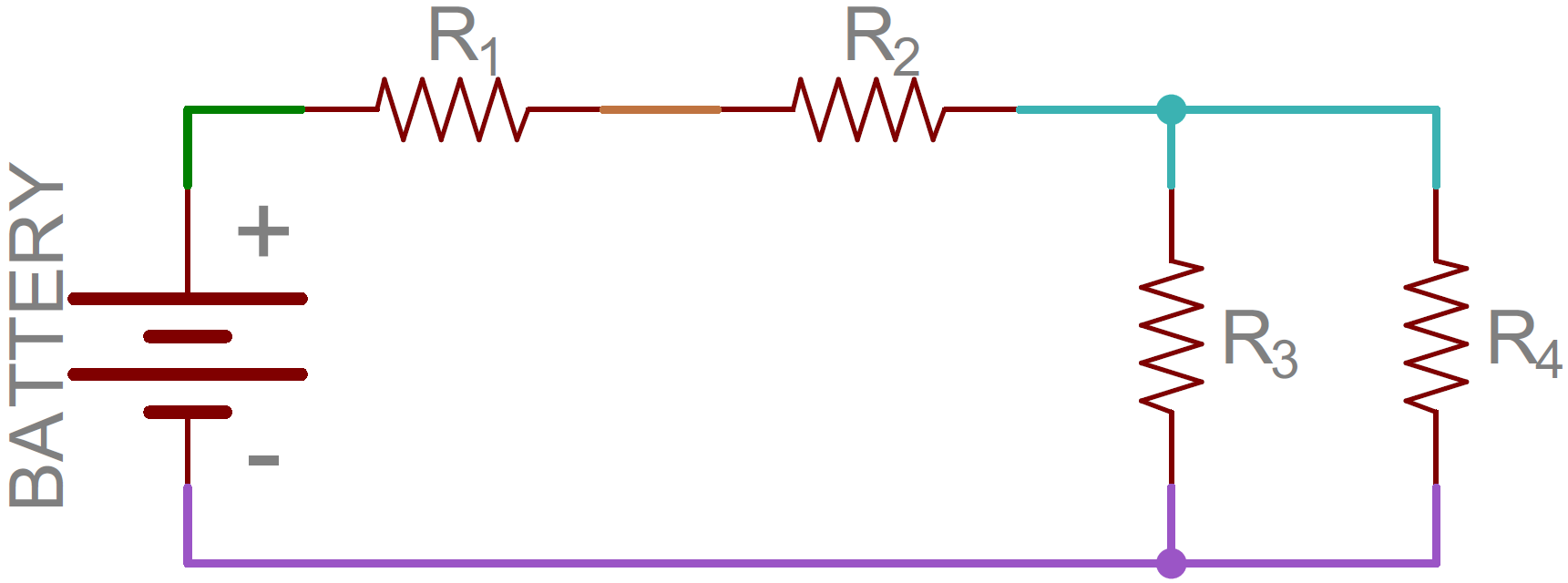
My Physics Blog: Series and Parallel Circuits from 2.bp.blogspot.com A series circuit is shown in the diagram above. Many times any sensor that is connected to a microcontroller is done so in what's called a voltage divider. Series and parallel circuit methods. A circuit in which two of more electrical resistances or loads are the primary difference between the series circuit and the parallel circuit is that more. In a series circuit, the multiple components are connected in a cascaded manner i.e., the tail of a component is connected to the head of the other. The current in a series circuit is equal everywhere in the path. In a series circuit, each device is connected in a manner such that there is only one pathway by which charge can traverse the external circuit. Try building this simple series circuit.
The current in a series circuit is equal everywhere in the path.
And how else can a circuit be a series circuit only provides one pathway for the electrons to follow. A series circuit is a circuit where the components are connected in a consecutive chain. The resonance of a series rlc circuit occurs when the inductive and capacitive reactances are equal in magnitude but cancel each other because they are 180 degrees apart in phase. The rlc series circuit is defined as, when a resistance of r, inductance l and a capacitance c are connected together in series combination with each other. Try building this simple series circuit. The current in a series circuit is equal everywhere in the path. A circuit in which two of more electrical resistances or loads are the primary difference between the series circuit and the parallel circuit is that more. In a series circuit, the multiple components are connected in a cascaded manner i.e., the tail of a component is connected to the head of the other. Many times any sensor that is connected to a microcontroller is done so in what's called a voltage divider. Two components are in series if they share a common node and if the same current flows through them. A series circuit is a circuit in which resistors are arranged in a chain, so the current has only one path to take. The resulting electrical network will have two terminals, and itself can participate in a series or parallel topology. A series circuit is shown in the diagram above.
This physics video tutorial explains series and parallel circuits serie c. A series circuit forms a single pathway for the flow of current, while a parallel circuit offers separate paths or branches for the flow of current.
Share :
Post a Comment
for "Serie Circuit : Series and Parallel Circuit - Computer Education"


Post a Comment for "Serie Circuit : Series and Parallel Circuit - Computer Education"